Invro Home
A new approach to copper electrorefining and electrowinning.
A new Patent Application û Electrorefining (ER) and Electrowinning (EW) of Copper
WhatÆs new?
A major evolution of the intercell busbar.
First the Walker, second the dogbone, and now the divided dogbone - creating space for meaurement and control with the cathode current in one place.
Also, we beat the problem of the incompatibility of tin-laden solder with arsenic-laden electrolyte in electrorefining.
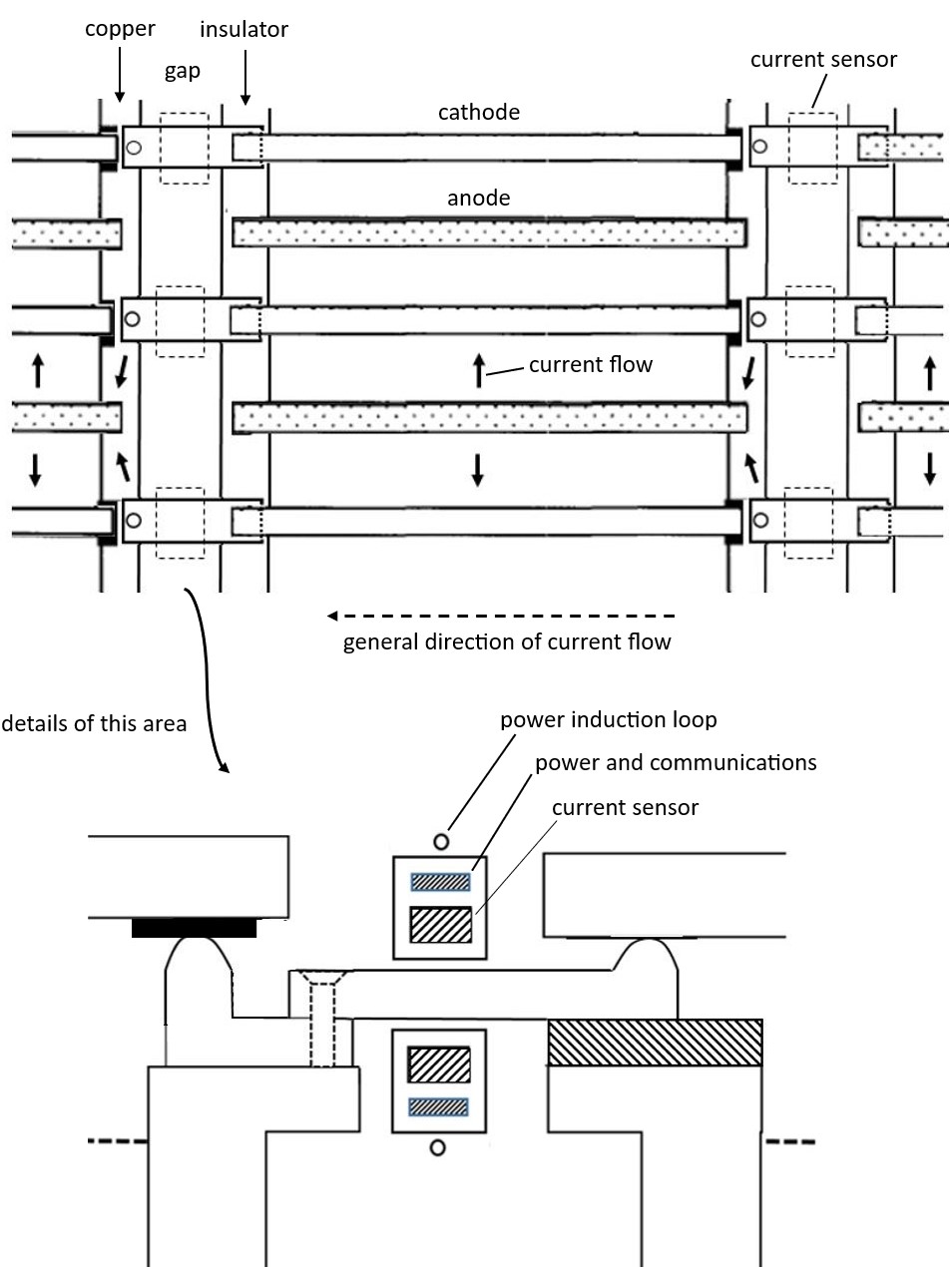
See an example at the end of this document for cathode current measurment in ER or EW.
Digitalisation and Current Sensing.
Everybody would like to get digitalisation into tankhouses. But it is hard. It is a harsh environment and tankhouses are big. A tankhouse of 200 tanks with 60 cathodes per tank will have a total of 24,000 current sensors if the current in every cathode is sensed. Some maintenance will be needed û replacing failed sensors. But the payoff is that the operators will know better what is going on and it should be possible to spot shorts before they cause damage or reduce productivity. Where to put the sensors? If the hanger-bar to intercell-busbar contact point is used there is no easy way to encircle the current flow and one ends up putting Hall sensors around the contact point, thus losing accuracy and increasing the device count. The patent application has a solution which permits the cathode current to be measured with an accuracy of 1% - good for all purposes.
Current control.
The patent idea also addresses this. A power MOSFET package can be introduced alongside the current sensor (in the same current path as the current sensor). It can be used in the on-off mode for protecting MMOAs in EW or anodes and cathodes and ER. LetÆs call this ôInterventionö. It can also be used to moderate current flow through a cathode (with suitable arrangements to permit it to act as a regulator). LetÆs call this ôCurrent Controlö. In theory, this can be used to get every cathode up to a higher current density than presently used. The main rectifier current can be increased while cathodes that tend to hog current can be limited to an ideal maximum value. Studies by La Universidad de Concepci¾n predict big improvements in tankhouse productivity if the current density dispersion (between cathodes) can be brought under control. However, beware. At the time of writing (2023) the lowest Rds(on) power MOSFET has an on-state resistance of about 250 ÁOhm. The resistance of the current path from a cathode to its associated anodes (i.e. through the electrolyte) is about 250 ÁOhm ( 0.2V/800A). Hence if the MOSFET switch uses ten MOSFETs in parallel it will have a resistance of 25 ÁOhm, so there will be an increase of about 10% in power loss. This may be a price worth paying for the production increase achieved.
Tin problem (ER)
It is common for the electrolyte in an ER tankhouse to contain significant amounts of arsenic. Tin is not welcome in such plant because if the tin enters the electrolyte there is a possibility that deadly arsine gas will be produced. Tankhouse managers recoil at the idea of even a tiny amount of tin being anywhere near the electrolyte. Electronics use either tin/lead solder (60/40) or lead free solder (typically 96% tin). The electronic units can be encapsulated in epoxy but with 24,000 units in a tankhouse (see above) it is understandable why tankhouse managers wonder how many will split or leak over the life of the tankhouse or its equipment. Power electronics (e.g. power MOSFET switches composed of 10 MOSFETs in parallel as hypothesised above ) typically contain a large amount of solder to provide the high current parallel connections required. In that case, one way û perhaps the only way û to provide some reassurance that tin and electrolyte will not meet is to locate the electronics between the tanks and below the tops of the tanks. This is another of the advantages claimed for the invention.
The patent application is presently without claims. There is potential to choose the subject of claim 1 or to file for a divisional (two patents with individual claims 1).
If this interests you, please feel free to contact me (duncan.grant@invro.com) to discuss. I can send you the complete description and drawings which have been filed with the UKPO.
Further Details of the Patent Application.
The aim of the invention is to make room in the dogbone for current sensing (and if required current management) by splitting the dogbone (which may require having or making some separation between tanks). The dogbone is split in the X-axis to make space for current sensing and control.
Then it is split in the Y-axis to put the currents heading to anodes or coming from cathodes into fingers. This provides an opportunity for 1% accuracy current sensing ûsuitable for all objectives. And intervention (preventing damage to anodes) and current management (get every cathode working optimally at maximum current density for more tankhouse throughput).
And finally there is displacement in the Z-axis (U-bend in the finger conductor) to get the electronics (signal and power) down between the tanks where there is negligible possibility of the parts entering the electrolyte (solving decisively the tin problem with ER).
Figure 1 shows a tank with the conventional Walker intercell busbar. Cathodes and anodes are offset from one another. The cathodes and anodes are fed from one end.
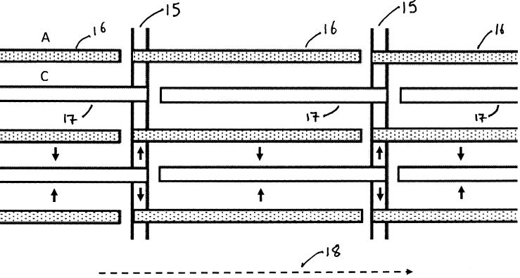
FIG1
15 Intercell busbar - Walker
16 Anode
17 Cathode
18 General direction of current flow
Figure 2 shows how a wider ôdogboneö intercell busbar is used. The cathodes and anodes now align. The cathodes and anodes are fed from one end. An equaliser intercell busbar may be used at the other end to help even out the current density dispersion (but is not an active feed). In all Figures a single-end feed is assumed for all electrodes. The circled area labelled X in this diagram is explored more in Figure 3.
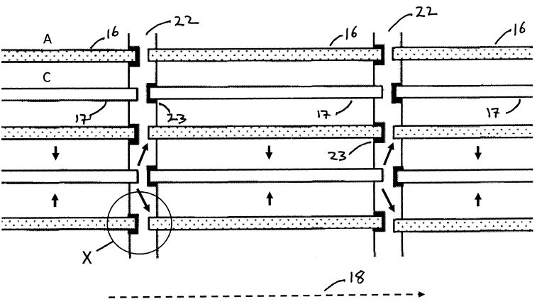
FIG 2
16 Anode
17 Cathode
18 General direction of current flow
22 Intercell busbar û dogbone
23 Insulator patch
Figure 3 is a cross section diagram at the area circled X in Figure 2
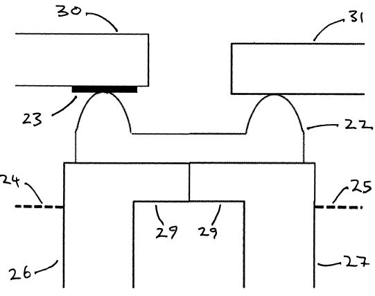
FIG 3
22 Intercell busbar û dogbone
23 Insulator patch
24 Electrolyte level
25 Electrolyte level
26 Tank wall
27 Tank wall
29 Tank wall lip
Figure 4 shows one aspect of the invention. The dogbone is extended using removable piece 37 (called a finger). The cross section shown here corresponds to the circled area Y in Figure 6. All the electrode current is in the finger and can be measured with 1% accuracy by the current sensor in the package 35. The sensor is powered inductively by the coil 40 and communication of the results is by short range radio.
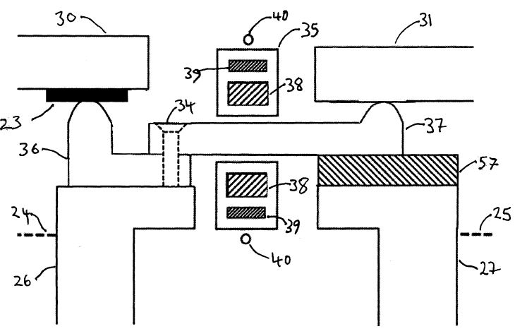
Fig 4
23 Insulator patch
24 Electrolyte level
25 Electrolyte level
26 Tank wall
27 Tank wall
30 Anode hanger bar
31 Anode hanger bar
34 Countersunk screw or bolt
35 Enclosed current sensor and PCB
36 Copper conductor bar
37 Finger conductor
38 Current sensor
39 PCB û comms and power
40 Inductive power driving coil
45 Encapsulation
57 Insulating strip
Figure 5 shows a cross section of the circled area Z in Figure 6
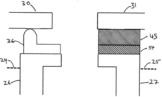
Fig 5
24 Electrolyte level
25 Electrolyte level
26 Tank wall
27 Tank wall
30 Anode hanger bar
31 Anode hanger bar
36 Copper conductor bar
57 Insulating strip
Figure 6 shows the layout when the anode currents are measured. Arrow 18 shows the general direction of current flow.
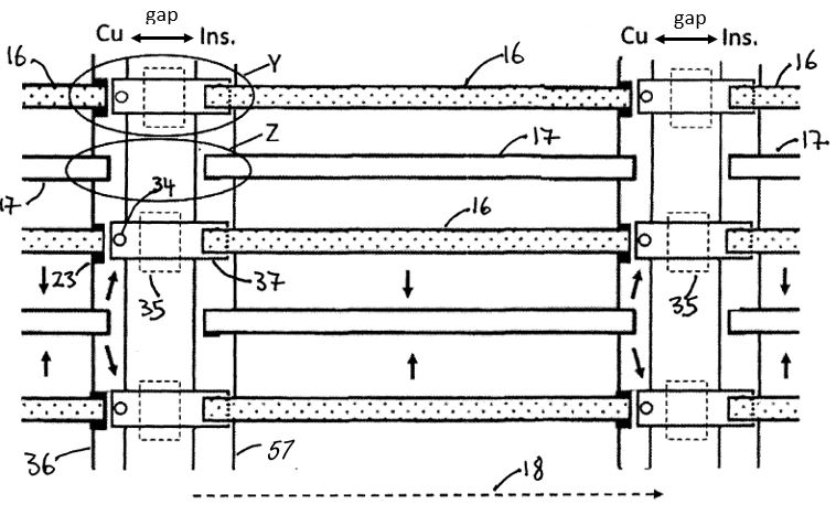
Fig 6
16 Anode
17 Cathode
18 General direction of current flow
23 Insulator patch
34 Countersunk screw or bolt
35 Enclosed current sensor and PCB
36 Copper conductor bar
37 Finger conductor
57 Insulating strip
Figure 7 shows the layout when the cathode currents are measured. Arrow 18 shows the general direction of current flow.
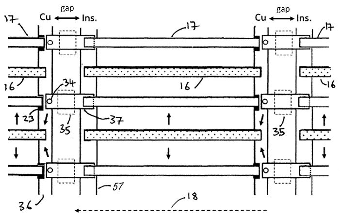
Fig 7
16 Anode
17 Cathode
18 General direction of current flow
23 Insulator patch
34 Countersunk screw or bolt
35 Enclosed current sensor and PCB
36 Copper conductor bar
37 Finger conductor
57 Insulating strip
Figure 8 shows another aspect of the invention. The finger section which carries the cathode or anode current bends below the tops of the tanks, making it very unlikely that any electronic unit will fall into a tank (and possibly cause an arsine gas incident). A power MOSFET pack acts as a switch or controls the flow of current into or out of the electrode.
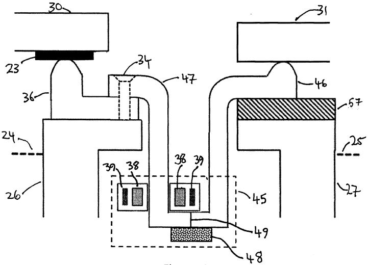
Fig 8
23 Insulator patch
24 Electrolyte level
25 Electrolyte level
26 Tank wall
27 Tank wall
30 Anode hanger bar
31 Anode hanger bar
34 Countersunk screw or bolt
36 Copper conductor bar
38 Current sensor
39 PCB û comms and power
45 Encapsulation
46 Second half of U-shaped finger
47 First half of U-shaped finger
48 MOSFET switch or Regulator
49 Insulating gap
57 Insulating strip
What a current measuring arrangement might look like.
A practical example of cathode current sensing.