Patents
Second Patent Filing
A second UK patent application was made on 13 February 2022. This comprises several new inventions relating to the implementation of the PowerMaximiser concept. Divisional applications based on this priority date are expected. Scroll down to "Second Patent Application" to see the text and drawing sources used for this application.
First Patent Filing.
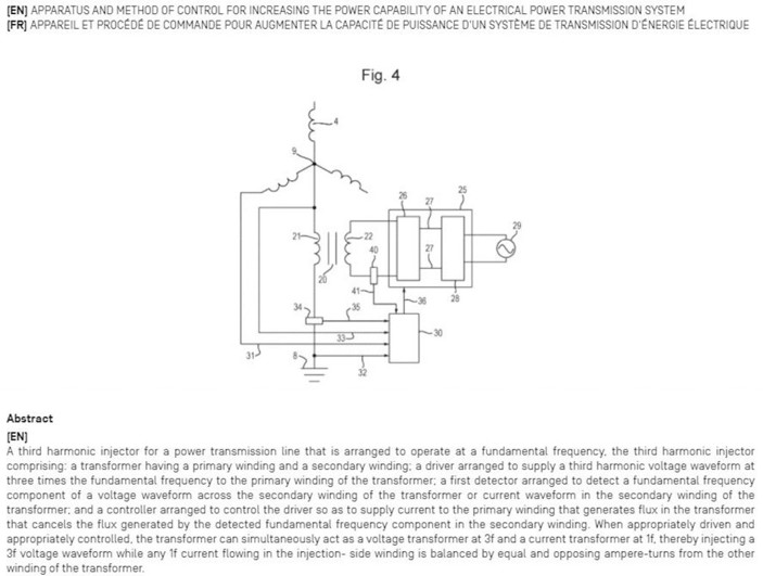
A patent application for the third harmonic star-point injector arrangement was filed with the UK patent office on 18 September 2019. "Apparatus and method of control for increasing the power capability of an electrical power transmission system". GB1913453.5. We received an encouraging report from the UK examination.
The key concepts in this application are:
The injector transformer operates as a voltage transformer at triple frequency and as a current transformer at fundamental frequency. This makes it appear transparent to fundamental frequency currents, particularly zero-sequence currents resulting from an unbalanced load on the transmission system.
Flux at fundamental frequency is suppressed in the injector transformer core by detecting any deviation of the transformer output voltage waveform from the desired triple frequency waveform and by the application of a corrective current in the input winding.
Fault-level currents are transiently handled by allowing the transformer to saturate thereby creating a low impedance connection to ground. Additional fault-handling capability is provided by an anti-parallel pair of SCRs across the transformer which are activated at the appropriate moment.
PCT Filing.
The patent application has gone forward to the PCT stage (PCT/GB2020/052257) and again the examination report was positive with respect to key claims.
The patent application was published on 25 March 2021. To see the application in full go to www.wipo.int/pctdb
and enter WO2021/053340
The application enters national phase in March 2022.
Strategy.
The national phase of securing a patent is an expensive activity. As is the building of demonstrators at the power levels commonly found in grid and distribution systems. Hence we are engaged in a partner search. We see the present priority to be the securing of further patents at this stage since we have additional ideas which are as yet unprotected but which have the potential to contribute further to the plug-and-play concept.
Patent Application Key Drawing and Abstract
Second Patent Application. (13 Feb 2022)
Increasing the power capacity of a three-phase electrical power transmission system by combining it with a triple-frequency power system.
Setting
Adding 1/6th third harmonic to the ac supply waveform (a sinusoid) permits the maximum theoretical power capability of a transmission system to be increased by 33%. Alternatively the power can be kept constant and voltage increased and the current reduced, thereby lowering line losses due to resistance by up to 33%.
Third harmonic injection gives some of the benefits of DC transmission while keeping the immense advantages of AC. Third harmonic injection in a section of a transmission system allows that section to operate for most of each cycle at close to peak allowable voltage. The technology is applicable to distribution systems as well as grid transmission.
Adding 1/6th of third harmonic lowers the peak value of a sinusoidal waveform by a factor of 0.866. Restoring the combined waveform to the allowable line-to-ground peak value for the transmission line raises the fundamental voltage by a factor of 1.156. This principle has been widely used for many years to raise the output voltage in three-phase inverters. ("The use of harmonic distortion to increase the output of a three-phase PWM inverter". Houldsworth J.A. and Grant D.A. IEEE Transactions of the Industry Applications Society, Sept 1984, pp 1224-1228). The P(max) of a power transmission line is proportional to V2. Therefore the raising of the fundamental voltage theoretically permits P(max) to be increased by a factor of 1.33. In Figure 2 the dashed line waveform 8 is the line-ground waveform before the addition of the third harmonic. The solid line waveform 9 is the line-ground voltage after the addition of the third harmonic and amplification by 1.156.
In conventional ac power systems which employ a pure sine wave, the line-to-line voltage is limited by the peak permitted line-to-ground voltage. By breaking that link by adding a third harmonic we allow the line-to line voltage to be increased by 15.6% and the power limit is increased by up to 33%.
The benefits of third harmonic addition are either more power capacity or reduced losses (if power transmission is kept the same and current is reduced in proportion to the voltage increase).
The third harmonic is stripped out as the power passes through the receiving end transformer. Or if it is advantageous, it can be retained and taken out later – or not at all depending on the end use.
A pure sine wave uses the maximum allowed line-ground voltage once every half cycle. A sine wave plus third harmonic uses the maximum allowed line-ground voltage twice every half cycle. Hence adding a third harmonic moves the performance of an ac line closer to that of a dc line. By adding third harmonic power transmission, fundamental power transmission is enhanced. To achieve the ideal voltage waveform along the whole line length, there must be power flow due to the third harmonic voltage waveform as well as power flow due to the fundamental frequency voltage waveform. So the process by which power flow due the 50Hz or 60Hz voltage waveforms is increased may be achieved by adding to the system power flow due to the 150Hz or 180 Hz voltage waveforms.
Means by which third harmonic voltage waveforms may be injected into a three-phase power line are described in patent application WO2021/053340
There are two modes in which a transmission line with third harmonic injection can be operated.
(1) Raise the power rating by up to 33% without raising the line-ground voltage rating. The fundamental line-line voltage is raised by 15.6%. P ∝ V2.
(2) Keep the power (VA) rating the same but reduce the line conductor losses. The fundamental voltage is raised by 15.6%. The current is reduced by 15.6%. I2R losses are reduced by 33%.
For a three-phase transmission line, power flow may approximately be expressed as:
P = V2 Sinδ / X
where
P is the total average power for the three phases
V is the working line-to-line voltage,
δ is the phase angle difference between the ends of the line
X is the reactance of the line.
Alternatively, the power flow may approximately be expressed as:
P = 3 V2 Sinδ / X
where:
P is the total average power for the three phases
V is the working line-to-ground voltage,
δ is the phase angle difference between the ends of the line
X is the reactance of the line.
In a three-phase transmission line in which only one (fundamental) frequency is employed, power is only due to positive sequence currents, the vectorial sum of which at each end of the line is zero. With no return current the line reactance per phase is approximately half the loop inductance of that of a 2-wire system (or equal to the inductance of a single side of the loop). It should be noted that while the inductance tends to dominate in a power line, resistance may be a significant component of the line impedance.
Expanding the equation P = 3 V2 Sinδ / X gives us some insights.
P = 3 x V x Vsinδ /X = 3 x Voltage(Line-Ground) x Current
The current in this equation is current at fundamental frequency. The in-phase component conveys power.
By adding a third harmonic and amplifying the waveform there is an immediate gain in Voltage (15.6%).
The current available is immediately increased by 15.6% (since it is a function of V in the equation above).
The amount of in-phase current which is caused to flow (node to node) is also determined
by how much we swing δ (or δ is swung for us – by the generator source or by quadrature voltage injection ). X is fixed. Stability considerations limit δmax.
Conductor losses may or may not be a limiting factor. Considerations include conductor weight, cost and sag). Some VAR flow is generated by a swing of δ. This is controllable by altering the relative magnitudes of Vsend and Vreceive. This voltage difference will also be needed to attend to the IR drop in each line.
Further details
Further details may be obtained from downloads of these patent applications from the relevant patent offices.